Sunday 7 June 2020

Tunnel


                       As an introduction though, why not go to the Blog overview first.

art@spitfireart.com

01273 843749 07976 312058

A look at the central tunnel panels.
All of these panels can be carpeted, and I recommend www.automobiletrim.com and their TCN/10 lining carpet. Alternatively, they can covered in vinyl or leather.

The angled tunnel cover allows slightly more "hip-room". The RHD drivers side is slightly narrower than the passenger side, not by much, just 40mm, but every mm on the hips is ..well, a bit more room! For LHD cars, this isn't a problem. if you visit www.aerobarrelback.blogspot.com you'll see how one client did a superb job covering his tunnel in vinyl. Note the bare metal chassis, this is for the authorities in Holland to inspect all welding integrity, after which they grant a new chassis number, enabling registration. Most UK and US clients go for a powder coated finish once the chassis has been blast prepared.

As an amendment 7/2/21, I bought a Caterham Seven 160 model (Suzuki 660cc turbocharged engine) in December 2020 and this is the narrow S3 model, and is this cockpit tight or what! I've always said to clients, if you can fit in a Caterham, then you can fit in one of mine! if not, just lose weight, It'll do you some good


A view looking forward from the rear on the Right hand side. Notice the rear tunnel cover angle, this remains on the RHS irrespective of RHD or LHD cars. Note the elongated slot through which the angled hand brake lever fits. The other exposed angled hole allows the main gear change lever to protrude.


Another view of the tunnel rear cover. Within the cut-out will lie the main rear bearing through which the rear propshaft passes down to the swing arm and final drive.


The angled tunnel panel has to transition through to a right angle, via the odd shaped piece shown above.


With the rear tunnel cover removed, the angled piece to which the hand brake lever bolts, can be seen.


Close-up of the hand brake lever location.


Close-up of the transition panel.


Just forward of the transition panel is the removable panel behind which, the reversing gearbox is situated, and it is bolted down to the angled plinth shown.


The forward RHS panel is also removable enabling access to fit/dismantle the front propshaft.


LHS forward panel which is riveted in place.


LHS removable panel, enables one to fill the reversing gearbox with oil, and to check oil level.


Intermediate rear LHS panel which is fully riveted in place.


Rear most small LHS panel is detachable and allows access for hand brake cable adjustment etc.


Final look at the LHS of the tunnel panels.


Sunday 10 November 2019


                           As an introduction though, why not go to the Blog overview first.


01273 843749 07976 312058


Rear of dashboard

Linked instrument lamps, linked back to main on/off  black Lucas style light switch.

Note linked earth cables to dashboard lamps. Read my notes concerning the main indicator stalk switch.


Saturday 9 November 2019

HUBS/WHEELS

                         As an introduction though, why not go to the Blog overview first.


01273 843749 07976 312058

Hubs/stub axles/wheels.
Specially manufactured to my specification, these are not "off the shelf " items. Splined hubs have been around since the firm Rudge Whitworth introduced them prior to WW1. Post WW1, many motor manufacturers began to use them, specifically MG and Riley in the 1930s, other manufacturers of sports cars following suit. I specifically wished to get the centre point steering/scrub radius, and in "old money" the king pin inclination angle as close as possible to the theory, which in effect is a line drawn through the top and bottom ball joints through to the steering arm ball joint, when projected, should intersect the centre of the wheel/tyre, or at least be close to it or to the tyres inner edge. Modern car wheels can more easily achieve this due to a large wheel offset.


These specially made alloy uprights use interference fit top hat inserts top and bottom into which the ball joints fit. I now modify the front top mudguard stay thread by drilling this out to 8mm all the way through, filing a flat on the opposite side, so that an 8mm bolt washer and nylock nut can be fitted.


Just a stub axle you might think, however I have these made to my own specification, again so that the wheel can be brought in on the hub to achieve the best possible KPI/scrub angle using 19 inch wire wheels.


Stub axle shown inserted into the upright.

Rear of the alloy upright showing a spacer. A nylock nut is fitted and torqued up to 50lbs.

A 5mm stainless steel spacer fits between the disc and the splined hub.

Disc/spacer/hub.


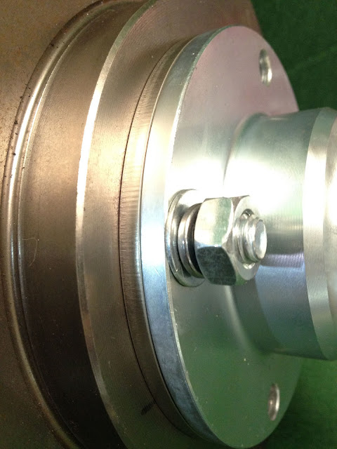
An interesting shot just to show the assembly bolted up with a wheel attached. In this shot it can be seen that the wheels are "outer laced", that is the spokes are to the outer of the wheel rim, rather than to the centre, as other wheels can be, and this brings the wheel in closer too, so that the KPI/scrub angle etc is maximised.

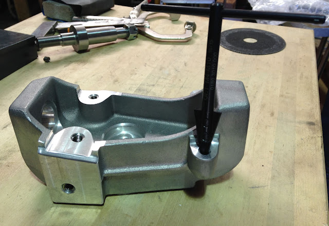
Now to the modification mentioned above. The tool shown inserted is a helicoil removal tool, just a triangular taper that grips the helicoil and unscrews it out. 6mm helicoils are inserted originally and I bolted mudguard stays at this point, but we've subsequently found that the 6mm bolts shear from vibration, so I decided to drill them out and hold the mudguard stay with an 8mm bolt and nylock nut.

Close up of the helicoil removal tool.

Here the upright is shown securely clamped on to the pillar drill table, enabling a perpendicular hole to be drilled. We've all tried drilling without securing things to a surface, always hold it down securely or accidents and damage can occur.


Here can be seen both uprights drilled through, before and after a flat has been filed so that a washer and nylock nut can be fitted holding the forward mudguard stay in place.


Finally the mudguard stay held by an 8mm socket cap head bolt, washer and nylock nut, which is much stronger than the original 6mm bolt in a blind hole. The mudguard stays look good when polished, and maybe the upright castings could be painted a contrasting colour?

Sunday 3 November 2019


                     As an introduction though, why not go to the Blog overview first.


01273 843749 07976 312058

An additional tool box idea.
I did this as a one off idea for a car built in 2018. It can easily be replicated at an additional cost. It can be used as a tool box or simply somewhere to put your lunch, or a change of underpants!


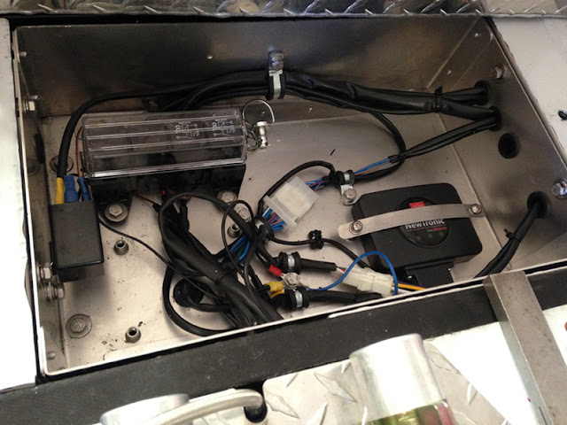
Here we see a basic electrics box and instantly it can be seen that this is a much earlier donor bike model with no fuel injection system, hence no ECU, however I did fit an electronic ignition system, a Newtronics unit, through to a distributor.


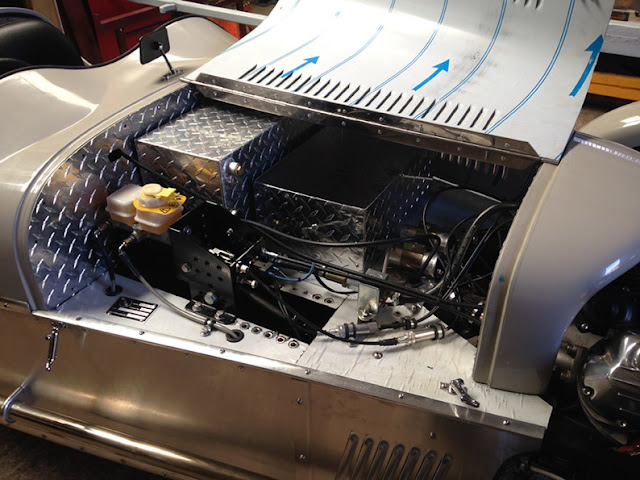
I decided to make up a box from the same "propellor" motif aluminium to sit in front of the tank, so it replicates the basic dimensions of the electrics box, but is taller, 160mm from memory. I wanted it to be fully detachable from the electrics box lid, so I fitted more Dzus fasteners to allow this. 

Here is another shot and in front can be seen the conventional ignition coils.


Here is the box shown from the other side. Note the throttle and chock cable "2 into 1" adaptors, which if one is a tinkerer, allows the owner to tinker with settings etc.


A distant shot.


Well, a box has to have a lid, so I folded one up and fixed it with more Dzus fasteners, and by this time, I was jolly excited!


Lid off, showing the Dzus fastener brackets. This reminds me of one of my funny stories, well not so since it cost me more money! I had four fuel tanks made up, all nicely Tig welded etc, but I'd forgotten to take into account the curvature of the bonnet and as the tanks had square edges the bonnet wouldn't shut, so they all had to be cut, corners trimmed and welded back at an angle. Then I forgot that a LHD car needs the tank moved over the other side, and the tanks can't be reversed, so had to have special LHD tanks welded up. After a few years or so, in fact this year to be precise, I stared at a tank, and thought...silly bugger, slope both sides and weld in 4 outlets, two of which can be capped off accordingly for a fuel injected version and 3 capped off for a carburettor version. The problem is now solved, but shows that eccentricity and lack of forethought can sometimes work in opposite directions!
What the hell, a box is a box.


One last shot of my nice box, and I didn't even charge the customer for it, he was a victim of my experimentation!