Fitting the indicators and rear lights. www.aerocyclecars.com
As an introduction though, why not go to the Blog overview first.

We are aiming to fit these indicator lamps, firstly to the headlights, bolted through the headlight bowls so that all wiring comes up through the headlights in one bundle. First of all unscrew the cowl and remove the bulb, then from under the shaped plinth, remove the nuts and withdraw the bolt from inside the lamp. Discard the bolt as we'll be using a 60mm M8 hollow thread.

Look down at the head lamp, notice the central M5 socket button head screw. Unscrew this and remove the glass, exposing the bowl interior.

From the centre point of the lamp (screw hole) lay a strip of masking tape, left or right, this photo shows a LH head lamp (as viewed from inside the car). Mark 75mm from the centre point, 12.5mm from the front edge. I use a flexible steel ruler that is precisely 12.5mm wide. A few words about rulers...I use rulers that are 12.5mm, 25mm, 30mm, 40mm and 50mm wide. This ensures that I simply pick up and mark out a width accordingly, the 12.5mm wide ruler is excellent for marking out midway up/down a 25mm chassis box member, then centre punching where one wishes to drill. Now, a few words about drilling thin stainless steel as in this head light bowl....not as easy as it might seem. use a centre punch first, then a small bit as a pilot, plenty of lubrication.
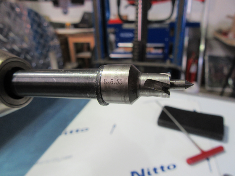
Here is an 8mm rotabroach cutter. These cutters are invaluable, they are mini hole saws. I have sets from 8mm to 20mm, plus a 25mm cutter and they are magnificent. Google ROTABROACH, then go to minicutters. The cutter above is used for drilling the 8mm hole through the headlight bowl cleanly.

Here are components we are going to use. 60mm M8 thread, nylock nut, spring washer, rubber washer, angled piece, then the flange and rubber previously removed, then insert into the headlamp bowl, second angled piece, then spring washer and standard M8 nut.

Here is how we'll bolt it up, remembering that the lowest 3 components are within the headlight bowl once assembled.

Here it is, all bolted up. Adjustment is quite fiddly, so take your time and keep checking it by placing a straight edge across the light bowls of both items. You'll need 2 x 13mm spanners for this and a lot of patience.

You are aiming for this, but there are variations, as we'll see in the next photo. Of course, you could move the measurements round to say 100mm or less, but more than 75mm.

This is the opposite side, but it looks wrong....it is, in my view, so re-position and move the angled pieces and the whole threaded piece in the hole to replicate the other side.

On to the rear lights now. No explanation, just centre punch at the above co-ordinates, and drill 8mm holes carefully.

Similar components as the front indicators, but this time do not use the plinths and rubbers, use the large stainless steel washers front and rear of the main side panels.

We are aiming to fit the components as shown above, but between the large washers is the main side panel of course.

This time you are routing 2 cables through the hollow threaded piece, and it is very tight, so make a screwing motion to guide the 2 cables through, then untwist them.

The fitting seen from inside the main side panel.

Repeat the exercise for the lower brake light/side light, then for the opposite side as well. Remember, take time to get the lamps sitting perfectly then tighten up carefully as the threaded hollow rod can be fragile.

Finally, you'll recall the holes drilled through the exhaust side pipe brackets in an earlier post. back drill through these brackets, then carefully through the side panels. use a piece of scrap in front of the side panel, but beware of your fingers.

Side clamp fitted.


