Tuesday, 25 October 2016

                                       Bonnet fitting time   www.aerocyclecars.com

As an introduction though, why not go to the Blog overview first.


I have the bonnet halves cut and louvred on a CNC Trumph machine, a £250K lump of kit, not mine you understand! Please remember....you do not have to do this, I bend these for you!

I mark each half suitably and owing to the different radii of the nose cone and the scuttle, make the first bend on a specially made cone. (first time I did this I was shitting myself!)


 The second bend is when it becomes exciting, over a 6 inch piece of plastic drain pipe.


A third tweak bend occurs around the nose cone end using a 3 inch drain pipe.

Suitably bent and the ends trimmed accordingly, time to fit the stainless steel hinge.


 Both bonnet halves shown hinged, even the starter body/chassis kit has the bonnets fully formed and hinge fitted. You will have to adjust the nose cone accordingly to reach nice looking shut lines.

  Both halves now laying over the GRP sections.


One side open, but not fitted yet.


The bonnet assembly can be removed easily as a whole by simply unscrewing the fitting shown here on the back of the nose cone.


Under bonnet shot showing petrol cap and bonnet clearance.

Wednesday, 5 October 2016

Fitting  the fuel tank   www.aerocyclecars.com

As an introduction though, why not go to the Blog overview first.


The alloy fuel tank sits up against the front upper bulkhead and is bolted down using M8 bolts, spring washers, washers to the tank support strap on the LHS and the LH pedal box support angle. M8 riv nuts need to be fitted/will have been fitted.


This shot shows the M8 riv nuts being fitted in the rear of the pedal box angled supports. Note the Masterfix ratchet riv nut tool,(also marketed by Wurth) which in my experience is the best manual riv nut tool without doubt...until I find a better one! I also use an air riv nut tool.


I've displayed this shot deliberately as it shows a potential hazard. I almost fell foul of my own mantra as I've not really allowed enough room for the tool when drilling the holes for the riv nut. You can see the tool just touching the steering column plate. One should always anticipate entry and exit of a tool when planning the position of a fixing...easily overlooked though.


Here is the LHS of the tank mounted down through the tank support plate into the tank support strap. The tank needs raising slightly to allow the electrics box cover to just slide under, so I've placed spacer plates under each side. Looking recently at photos of the best client built car, and I always look for details, in my view the above bolts should be replaced with socket cap head bolts.


These last two shots show the tank in position, bolted down with M8 bolts, spring washers and washers. The tank can be removed as can the plate beneath, thus giving additional access into the tunnel. Remember, for LHD, these photos would be reversed.


                        Fitting  the front mud guards/wings/fenders.   www.aerocyclecars.com

As an introduction though, why not go to the Blog overview first.
See SAFETY UPDATE further down re 6mm SCH screw/bolt.


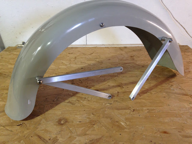
Here is a mudguard complete with all stays fitted. The pictures below show how it is all mounted up.

This shot shows the rear of the mudguard with the upper and lower stays fitted. Please note that a later post shows that one of the stays has now been superceded.


This shot shows the front stay fitted together with the angled spacer. The sequence for assembly of the upper fixture is: M8 55mm SBH (socket button head screw), washer, stay, angled spacer, washer, mud guard, radiused stiffener (already fitted), washer, 8mm nylock nut.


Looking inside the mudguard, the radiused stiffener piece is visible to which the stays are bolted. Note that for the purpose of this picture, nylock nuts are not shown, but must be used in reality.


First thing is to identify the three different lengths of mudguard stay. The radiused stiffener will already have been fitted to the mudguard. The shorter but thicker stay is for the front.


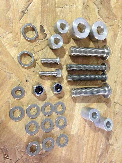
Identify all of the components required for assembly.


This shot shows the 2 rear stays fitted. The sequence is as follows: Identify M8 - M6 stay and M8 - M12 stay. M8 55mm SBH, washer, M8-M6 stay, M8-M12 stay, M8 10 x 16 spacer, washer, mud guard, radiused stiffener, washer, nylock nut.


This shot shows the M6 fitment of the upper stay into the upper position of the alloy upright. The shot below shows this in close up. All bolts/screws into the alloy upright must be held by Locktite or similar.


All bolts/screws into the alloy upright must be held by Locktite or similar.


This shot shows the lower M6 SCH (socket cap head screw) into the forward position. 
All bolts/screws into the alloy upright must be held by Locktite or similar.
Safety Update 24/10/18: The 20mm M6 SCH screw/bolt should be changed to a standard 8.8/12.8 SCH screw/bolt as stainless steel SCH 6mm screw/bolts in this position have been found to shear.


This shot shows the M8-M12 stay bolted into the brake caliper and the alloy upright. The sequence is as follows: M12 SBH 50mm screw, spring washer, stay, M12 25 x 10 alloy spacer, through the caliper into the alloy upright.
All bolts/screws into the alloy upright must be held by Locktite or similar.


Side view of mud guard mounted up.


Rear view of mounted mud guard.